Fire Pump Control Automation Project
| Fire Pump Control Automation Project |
||
|
|
 |
 |
|
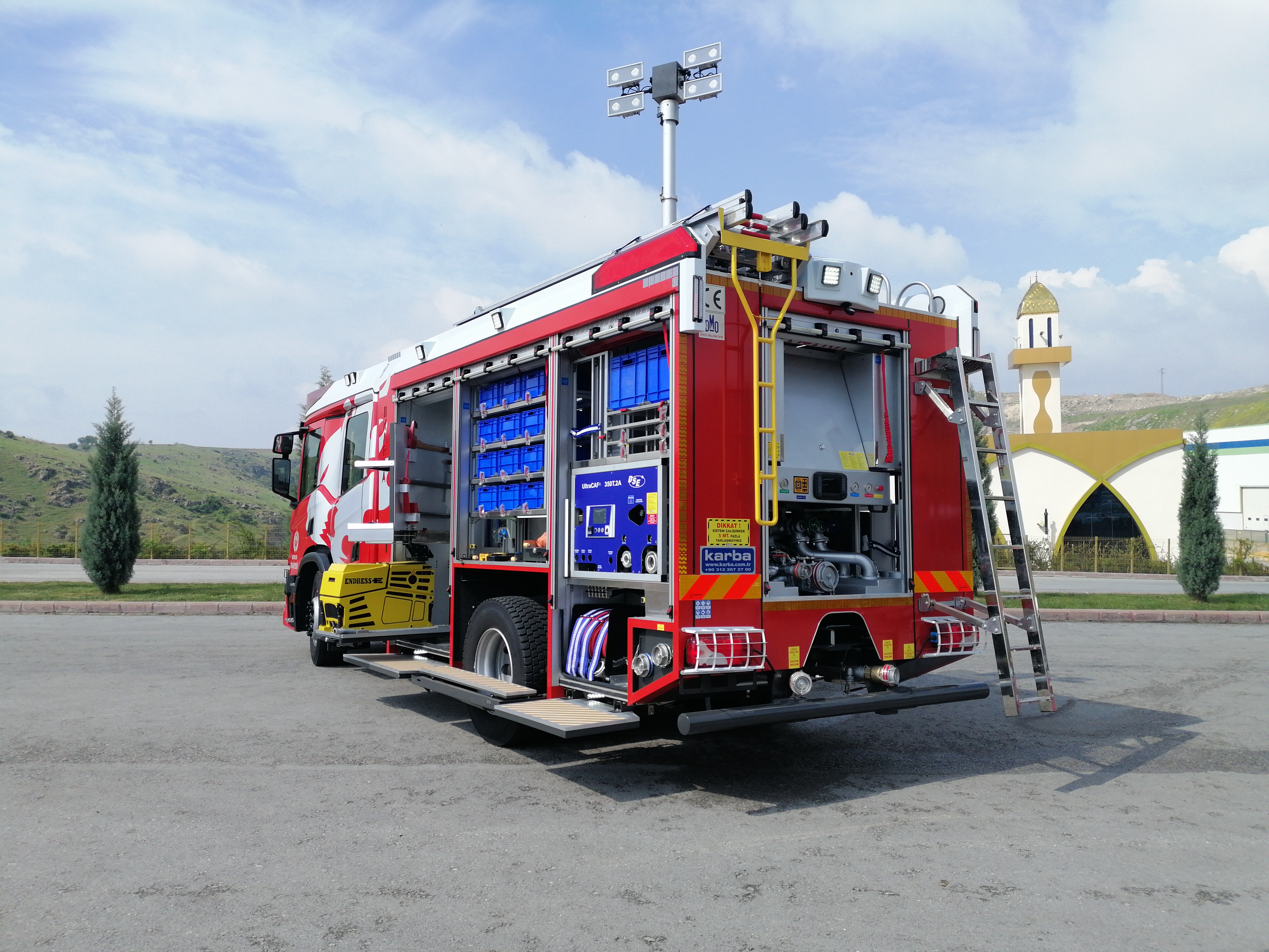
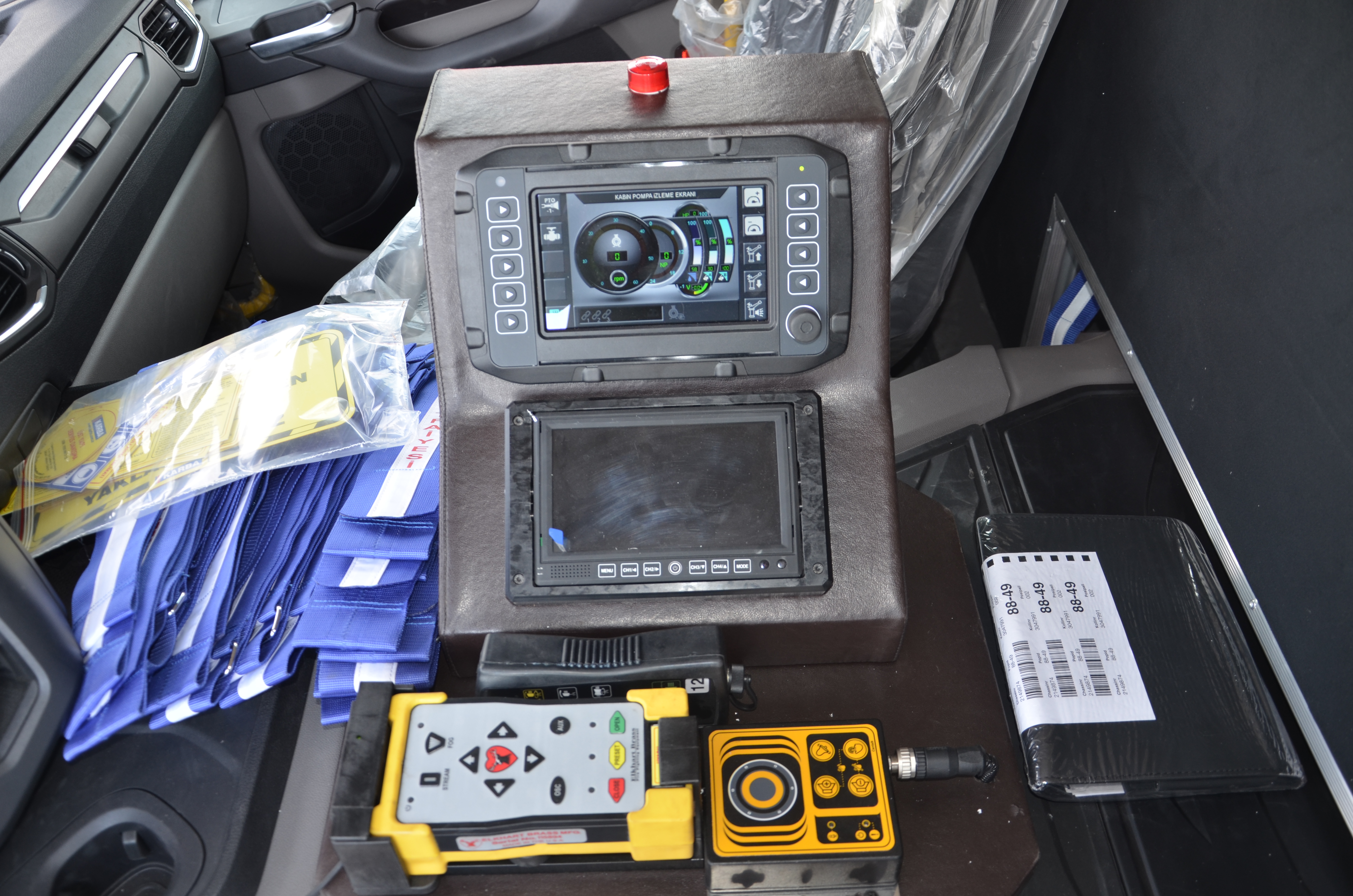
This system has customer specific functions and graphic designs. It’s controlled all water (fire) pump, working lights and engine functions. Motor control and visualization functions, fire pump control and visualization functions, CAFS system visualization functions and control of lighting functions by using 1 automotive class control unit and 2 pieces 7 ”touch screen. (1 in cabin side and 1 in pump side) The controls to be carried out and the systems to be displayed in the project consist of 4 main sections. Vehicle Engine Information display and throttle control VEHICLE ENGINE INFORMATION DISPLAY AND GAS CONTROL The vehicle must have a CAN J1939 engine. The model and engine information and the technical information of the CAN J1939 system to be used in the system must be provided by the customer and shared with EHR Electronics. The engine is controlled by the EHR automation system via the engine ECU via the engine manufacturer (D +) signal terminals for Throttle, Throttle reduction, Rolanti, Engine Start, Engine Stop, Engine running (D +). LIGHTING SYSTEM INFORMATION DISPLAY AND LIGHTING FUNCTIONS The control of 10 lighting projectors on the vehicle is carried out by the system. In addition, ceiling lighting, under-vehicle lighting, interior lighting can be controlled via the screen in the driver’s seat and the screen in the pump room. The status of the flasher lamps is displayed on the cab display. CONTROL OF FIRE PUMP FUNCTIONS AND DISPLAYING PUMP INFORMATION Monitoring of the valves and sensors in the fire pump and the requested functions are performed by the system. DISPLAY OF CAFS SYSTEM INFORMATION The information provided by the CAFS system manufacturer is displayed on the respective screens. |
||