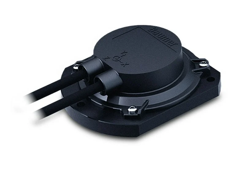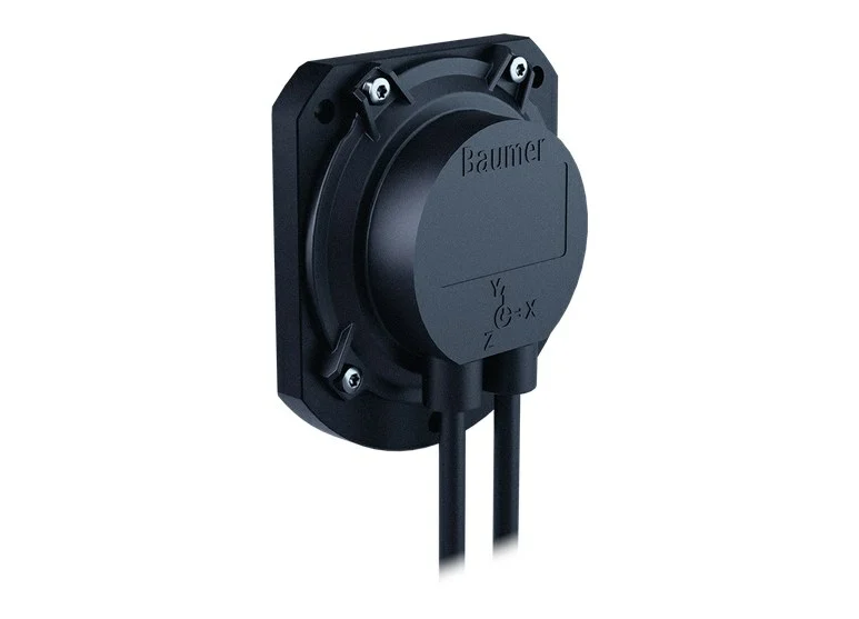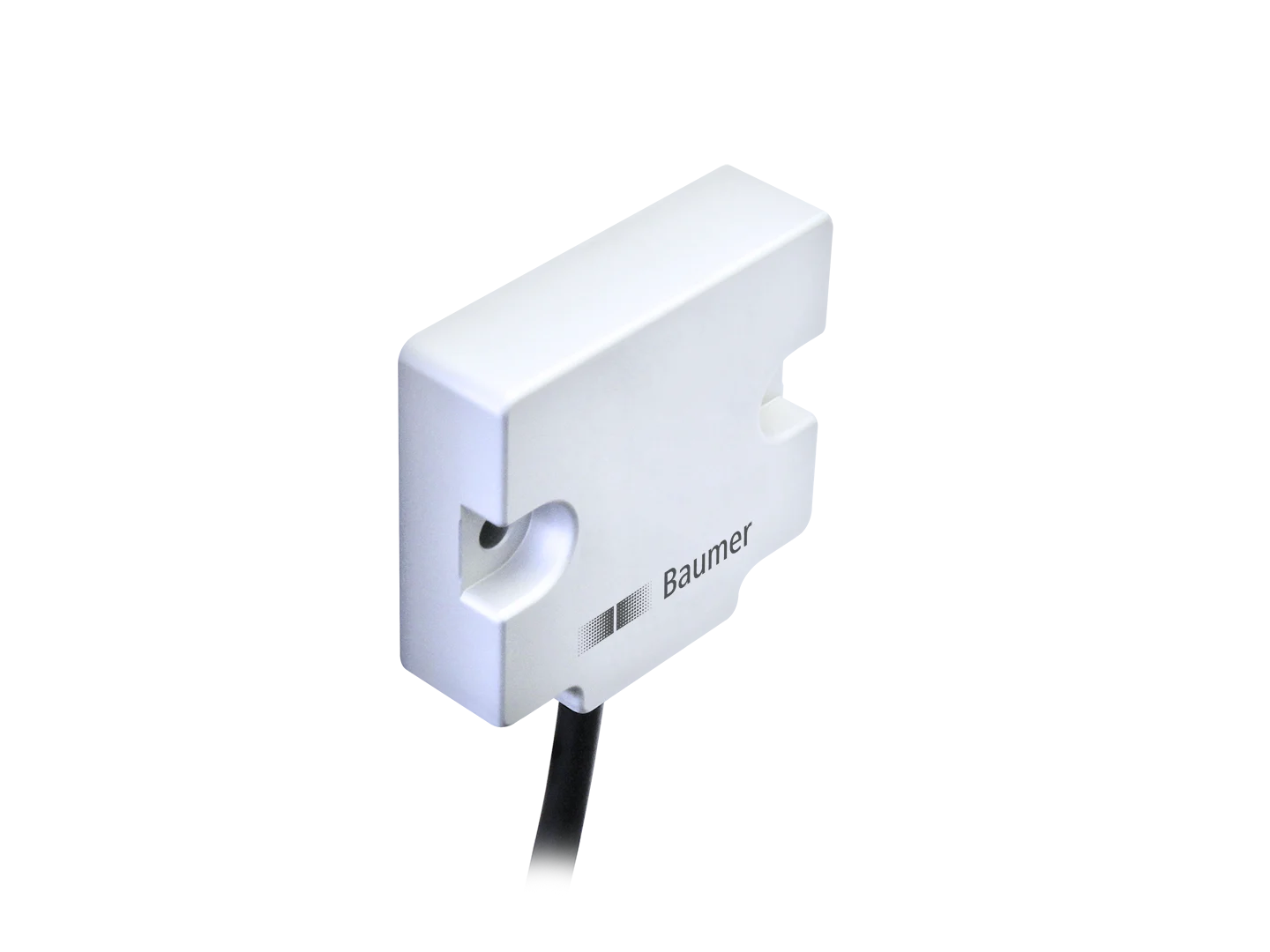
Highlights
- 1-dimensional, measuring range 0…360°
- Size 48 mm
- MEMS capacitive measuring principle
- Interface CANopen® / CANopen® redundant
- Protection up to IP 69K
- Corrosion protection CX (C5-M)
- E1 approval (KBA), UL approval
- Load dump protection
- Connection cable and cable with M12
- Wire cross section 0.5 mm²
- Redundant version (2-channel architecture)
Technical Specifications
| Technical data – electrical ratings | |
|---|---|
| Voltage supply | 8…36 VDC |
| Reverse polarity protection | Yes |
| Short-circuit proof | Yes (28 VDC or ground) |
| Consumption typ. | 28 mA (24 VDC, w/o load); 56 mA (24 VDC, w/o load, redundant) |
| Initializing time | ≤ 0.5 s after power on |
| Interface | CANopen® |
| Measuring range | 0…360° |
| Resolution | 0.1 ° |
| Accuracy (+25 °C) | Typ. ±0.2° |
| Temperature coefficient | 0.01 °/K |
| Sensing method | MEMS technology |
| Repeatability | ± 0.1 ° (+25 °C) |
| Sensing rate | 1600 Hz (0.625 ms) |
| Limit frequency | 0.1…25 Hz, 2. order / low-pass filter (Default: 2 Hz) |
| Output stages | CAN-Bus compatible ISO 11898 |
| Load dump protection | ISO 16750-2; Test Level A, 12 V / 24 V systems |
| Interference immunity | EN 61000-6-2; ECE Reg. No. 10R06; ISO 7637-2 |
| Emitted interference | EN 61000-6-3; ECE Reg. No. 10R06; ISO 7637-2 |
| Programmable parameters | Preset and offset; Filter |
| Approval | E1-type; UN ECE 10R06; UL approval / E217823 |
| Technical data – mechanical design | |
| Dimensions W x H x L | 48 x 14 x 45 mm |
| Protection EN 60529 | IP 67; IP 69K |
| Material | Housing: aluminium, anodised |
| Corrosion protection | IEC 60068-2-52 Salt mist; for ambient conditions CX (C5-M) according to ISO 12944-2 |
| Operating temperature | -40…+85 °C |
| Resistance | EN 60068-2-6; Vibration 20 g, 58-2000 Hz; EN 60068-2-27; Shock 50 g, 6 ms |
| Temperature changes | EN 60068-2-14, -40…+85 °C, 5 cycles |
| Weight approx. | 45 g |
| Connection | Cable 0.3 m; Cable 0.3 m with connector M12 |
Order code
| GIM140R-M136.SC8.A | Version in our stock |
CANopen® features
- Profiles: communication profile DS 301 V4.2, inclinometer profile DS 410 V1.3, Layer Setting Services (LSS) DSP 305 V3.0
- Default settings: resolution 0.1°, baud rate 250 kbit/s, Node-ID 1 and Node-ID 2, timer-driven transmission 100 ms
- PDO 1 content: temperature and inclination angle; the angle is transmitted in steps of 0.1°
Connection and pin assignment
Connection options: 0.3 m cable or 0.3 m cable with M12 connector (5-pin; the data sheet also lists a cable connection with 2 x M12, 5-pin). M12 connector pin assignment:
| Pin 1 | CAN_GND (ground connection relating to CAN) |
| Pin 2 | +Vs (voltage supply) |
| Pin 3 | GND (ground connection relating to +Vs) |
| Pin 4 | CAN_H (CAN bus signal, dominant high) |
| Pin 5 | CAN_L (CAN bus signal, dominant low) |
Cable core colours
| White | GND |
| Brown | +Vs |
| Green | CAN_H |
| Yellow | CAN_L |
| Grey | CAN_GND |
- Cable: 5 x 0.5 mm²
- Terminals of the same significance are internally connected and identical in their functions; maximum load on the internal Vs-Vs and GND-GND connections is 0.5 A each.
Installation and commissioning notes
- The rotational axis must be perpendicular to the ground; maximum misalignment ±5°.
- The default position is 0°.
- When operating close to the maximum limits, the actual temperature at the housing must be measured.
- Vibration in the range of 1600 Hz reduces measuring accuracy.
Options
- Integrated terminating resistor
- Connection with DEUTSCH or AMP connector on the cable end
Listed as options in the data sheet; contact us for options beyond the version we keep in stock.
Browse other Baumer products or the Sensors category. Related models: Baumer GIM600R-N136, Baumer GIM600DR-N136.
We offer delivery from stock in Türkiye and local technical support.
 Baumer GIM140R Inclination Sensor – Data sheet (PDF)
Frequently asked questions
Which CANopen® profiles does the GIM140R support?
According to the data sheet: communication profile DS 301 V4.2, inclinometer profile DS 410 V1.3 and Layer Setting Services (LSS) DSP 305 V3.0.
What are the default baud rate and Node-ID?
The default resolution is 0.1°, the baud rate 250 kbit/s, with Node-ID 1 and Node-ID 2; transmission is timer-driven at 100 ms.
What are the cable core colours and the pin assignment?
White GND, brown +Vs, green CAN_H, yellow CAN_L, grey CAN_GND. On the M12 5-pin connector: pin 1 CAN_GND, pin 2 +Vs, pin 3 GND, pin 4 CAN_H, pin 5 CAN_L; cable 5 x 0.5 mm².
In which orientation should it be mounted?
The rotational axis must be perpendicular to the ground; the maximum misalignment is ±5°. The default position is 0°.