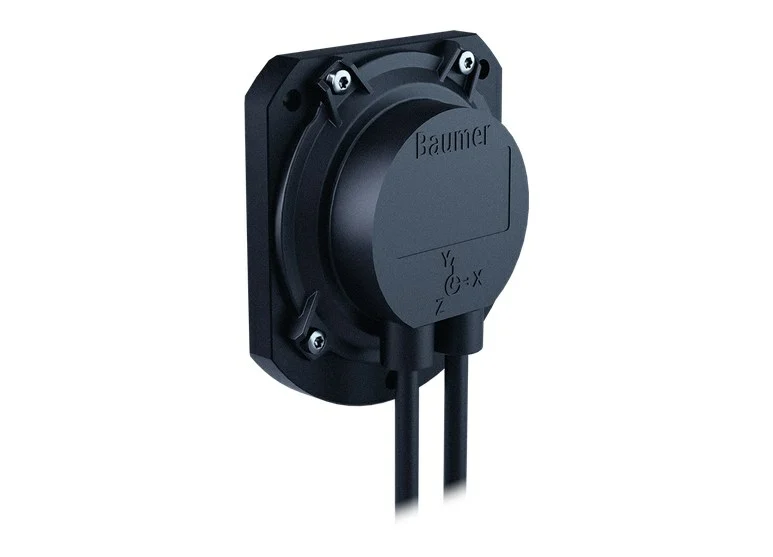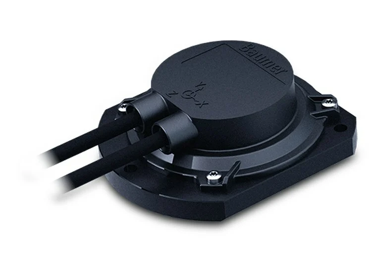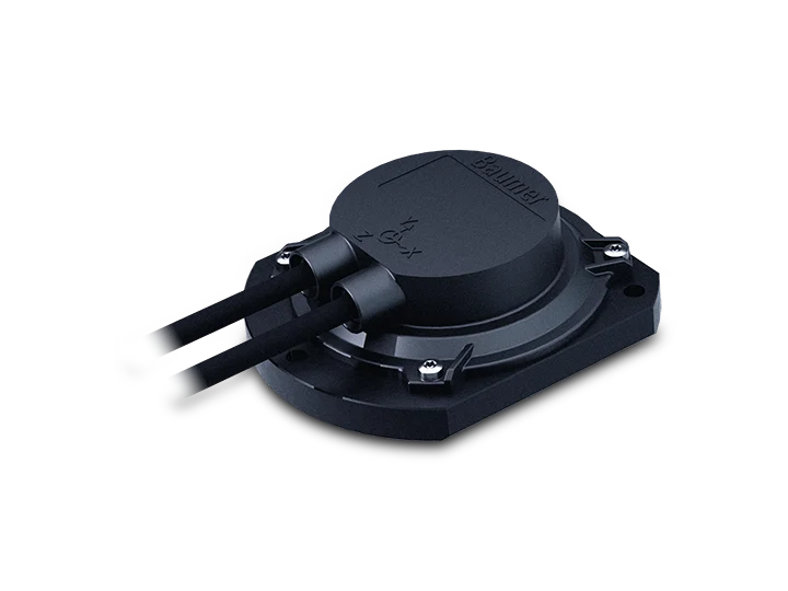
Highlights
- 2-dimensional, measuring range up to ±90°
- High measurement accuracy in dynamic applications
- Sensor fusion for gyro-based motion compensation
- Designed for mobile machines
- E1 compliant design
- Load dump protection
- Protection up to IP 69K
- Corrosion protection CX (C5-M)
- Connection cable / cable with M12 connector
- Interface CANopen®
- Redundant versions (2-channel architecture)
Technical Specifications
| Technical data – electrical ratings | |
|---|---|
| Voltage supply | 8…36 VDC |
| Reverse polarity protection | Yes |
| Short-circuit proof | Yes |
| Consumption typ. | 30 mA (24 VDC, w/o load, redundant) |
| Initializing time typ. | ≤ 1 s after power on |
| Interface | CANopen® |
| Measuring range | ±90° |
| Resolution | 1 … 0.001 ° |
| Dynamic accuracy typ. | ±0.5° |
| Static accuracy typ. | ±0.1° (+25 °C) |
| Static accuracy max. (horizontal) | ±0.28° (+25 °C); ±0.42° (0…+50 °C); (measuring range ±10°) |
| Sensing method | MEMS technology |
| Sensing rate | 1000 Hz (1 ms) |
| Output stages | CAN-Bus compatible ISO 11898 |
| Load dump protection | ISO 16750-2 for 12 V / 24 V systems; Pulse 5b (test criteria B) |
| Interference immunity | EN 61000-6-2; ISO 7637-2*; ISO 7637-3*; ISO 11452-2*; ISO 11452-4*; ISO 11452-5*; EN 61000-4-2 (CD ±8 kV, AD ±15 kV); * Severity level according to ECE R10 (Rev. 6 + Amd 02:2021-12) |
| Emitted interference | EN 61000-6-3; EN 61000-6-4; ISO 7637-2*; CISPR 25:2008 (30…1000 MHz); * Severity level according to ECE R10 (Rev. 6 + Amd 02:2021-12) |
| Programmable parameters | Preset / zero position; Resolution; Rotating direction |
| Diagnostic function | Supply voltage monitoring; Temperature control |
| Approval | UL approval / E217823 |
| Technical data – mechanical design | |
| Dimensions W x H x L | 72 x 24 x 64 mm |
| Protection EN 60529 | IP 66; IP 67; IP 68 (without connector); IP 69K (without connector) |
| Material | Housing: polyamide (glass fiber reinforced); Base plate: metal |
| Corrosion protection | IEC 60068-2-52 Salt mist; for ambient conditions CX (C5-M) according to ISO 12944-2 |
| Operating temperature | -40…+85 °C |
| Resistance | EN 60068-2-6; Vibration 30 g, 60-2000 Hz; EN 60068-2-27; Shock 100 g, 6 ms; EN 60068-2-64; Random vibration 10 gRMS, 20-1000 Hz |
| Temperature changes | EN 60068-2-14, -40…+85 °C |
| Weight approx. | 150 g |
| Connection | Flylead connector 2xM12, 5-pin, (Bus-in/Bus-out), length 300 mm |
Order code
| GIM600DR-N290.PC8.A | Article no. 11731016 |
Dynamic measurement approach
The GIM600DR incorporates 6-DOF MEMS sensors for acceleration and rotation. According to the data sheet:
- Inclination measurement in two axes with compensation of external accelerations
- High signal quality and fast response time thanks to powerful, field-proven sensor fusion algorithms
- Six-degree-of-freedom inertial measurement unit (IMU)
- Raw data output for acceleration and rotation rate
The manufacturer states that the rugged design offers highest availability under the harshest environmental conditions.
CANopen® features
- Profiles: CANopen® CiA DS 301 V4.2, inclinometer profile DS 410 V2.0, LSS service profile DS 305 V3.0
- Default settings: resolution 0.1°, baud rate 250 kbit/s, Node-ID 1 (Node-ID 2 on the redundant version), time-driven transmission 100 ms
- PDO 1 content: temperature and the inclination angles of the X axis (slope long) and Y axis (slope lateral)
- Secondary data: acceleration (resolution 0.1 mg; range -3.2768…+3.2767 g), rotation rate (0.01 dps; range -327.68…+327.67 dps) and Euler angles (0.01 deg; range -180°…+180°)
- Listed as options in the data sheet: Euler angle / quaternion output and 3-axis acceleration / rotation rate output can be PDO-mapped. Contact us to find out which version offers them.
Connection and pin assignment
Connection: flylead connector 2 x M12, 5-pin (Bus-in / Bus-out); M12 flange connector (male/female), A-encoded.
| Pin 1 | CAN_GND (ground connection relating to CAN) |
| Pin 2 | +Vs (voltage supply) |
| Pin 3 | GND (ground connection relating to +Vs) |
| Pin 4 | CAN_H (CAN bus signal, dominant high) |
| Pin 5 | CAN_L (CAN bus signal, dominant low) |
- The GND and CAN_GND terminals are internally connected and identical in their functions.
- Maximum load on the Vs and GND terminals is 1.5 A each; the daisy chain current is max. 1.5 A.
Installation and commissioning notes
- The base plate must be aligned parallel to the horizontal line. The X and Y axes can each be inclined relative to the horizontal plane; one measured value is supplied for each axis.
- Reference the zero position of the sensor after installation and check the zero-point stability regularly while installed.
- Dynamic accuracy depends on the characteristics of the movement patterns in the application; validating the sensor performance in the application is highly recommended.
- Self-heating must be considered for precise thermal design; approximately 5 K applies when mounted on a painted metal base. When operating close to the maximum characteristic values, the actual temperature at the sensor housing must be measured.
Browse other Baumer products or the Sensors category. Related models: Baumer GIM600DR-N136, Baumer GIM600R-N290.
 Baumer GIM600DR-N290 Dynamic Inclination Sensor – Data sheet (PDF)
Frequently asked questions
Which CANopen® profiles does the GIM600DR-N290 support?
According to the data sheet: CANopen® CiA DS 301 V4.2, inclinometer profile DS 410 V2.0 and LSS service profile DS 305 V3.0.
What are the default baud rate and Node-ID?
The default resolution is 0.1°, the baud rate 250 kbit/s and the Node-ID 1; the redundant version uses Node-ID 2. Transmission is time-driven at 100 ms by default.
Can acceleration, rotation rate and Euler angle data be obtained?
According to the data sheet, acceleration, rotation rate, Euler and quaternion values are additionally available; Euler angle / quaternion and 3-axis acceleration / rotation rate outputs can be PDO-mapped as options. Contact us for details.
Is the dynamic accuracy the same in every application?
No. According to the data sheet, dynamic accuracy depends on the characteristics of the movement patterns in the application; validating the sensor performance in the application is highly recommended.
What should be considered after installation?
The base plate must be aligned parallel to the horizontal line, the zero position must be referenced after installation and the zero-point stability should be checked regularly while installed.