OBD – On-board diagnosis
OBD – On-board diagnosis
On-board diagnostics (OBD) is an automotive term referring to a vehicle’s self-diagnostic and reporting capability. OBD systems give the vehicle owner or repair technician access to the status of the various vehicle subsystems. The amount of diagnostic information available via OBD has varied widely since its introduction in the early 1980s versions of on-board vehicle computers. Early versions of OBD would simply illuminate a malfunction indicator light or “idiot light” if a problem was detected but would not provide any information as to the nature of the problem. Modern OBD implementations use a standardized digital communications port to provide real-time data in addition to a standardized series of diagnostic trouble codes, or DTCs, which allow one to rapidly identify and remedy malfunctions within the vehicle.
History
1968: Volkswagen introduces the first on-board computer system with scanning capability, in their fuel-injected Type 3 models.
1978: Datsun 280Z On-board computers begin appearing on consumer vehicles, largely motivated by their need for real-time tuning of fuel injection systems. Simple OBD implementations appear, though there is no standardization in what is monitored or how it is reported.
1980: General Motors implements a proprietary interface and protocol for testing of the Engine Control Module (ECM) on the vehicle assembly line. The ‘assembly line diagnostic link’ (ALDL) protocol broadcasts at 160 bit/s. Implemented on California vehicles for the 1980 model year, and the rest of the United States in 1981. In most cases, the ECM (Engine Control Module) can be made to display DTCs (Diagnostic Trouble Code(s)) as a flashing pattern on the CEL (Check Engine Lamp) or MIL (Malfunction Indicator Lamp). A PC based Software package called WinALDL will listen to the CLCC (Closed Loop Carburetor Control) and early CLC EFI datastreams over a fairly easy to construct interface cable that converts the 160 baud TTL serial data being transmitted by the ECM to RS232 or USB serial data but there is not much information transmitted by these early ECMs.
1986: An upgraded version of the ALDL protocol appears which communicates at 8192 bit/s with half-duplex UART signaling. This protocol is defined in GM XDE-5024B.
1988: The Society of Automotive Engineers (SAE) recommends a standardized diagnostic connector and set of diagnostic test signals.
1991: The California Air Resources Board (CARB) requires that all new vehicles sold in California in 1991 and newer vehicles have some basic OBD capability. These requirements are generally referred to as “OBD-I”, though this name is not applied until the introduction of OBD-II. The data link connector and its position are not standardized, nor is the data protocol.
1994: Motivated by a desire for a statewide emissions testing program, the CARB issues the OBD-II specification and mandates that it be adopted for all cars sold in California starting in model year 1996 (see CCR Title 13 Section 1968.1 and 40 CFR Part 86 Section 86.094). The DTCs and connector suggested by the SAE are incorporated into this specification.
1996: The OBD-II specification is made mandatory for all cars manufactured in the United States to be sold in the United States.
2001: The European Union makes EOBD mandatory for all gasoline (petrol) vehicles sold in the European Union, starting in MY2001 (see European emission standards Directive 98/69/EC).
2003: The European Union makes EOBD mandatory for all diesel cars sold in the European Union
2008: Certain light vehicles in China are required by the Environmental Protection Administration Office to implement OBD (standard GB18352) by July 1, 2008. Some regional exemptions may apply.
2010: HDOBD (heavy duty) specification is made mandatory for selected commercial (non-passenger car) engines sold in the United States.
OBD II
OBD-II is an improvement over OBD-I in both capability and standardization. The OBD-II standard specifies the type of diagnostic connector and its pinout, the electrical signalling protocols available, and the messaging format. It also provides a candidate list of vehicle parameters to monitor along with how to encode the data for each. There is a pin in the connector that provides power for the scan tool from the vehicle battery, which eliminates the need to connect a scan tool to a power source separately. However, some technicians might still connect the scan tool to an auxiliary power source to protect data in the unusual event that a vehicle experiences a loss of electrical power due to a malfunction. Finally, the OBD-II standard provides list of standardized DTCs. As a result of this standardization, a single device can query the on-board computer(s) for these parameters in any vehicle. OBD-II standardization was prompted to simplify diagnosis of increasingly complicated emissions equipment, and though only emission-related codes and data are required to be transmitted through it according to U.S. legislation, most manufacturers have made the OBD-II Data Link Connector the main connector in the vehicle through which all systems are diagnosed and reprogrammed. OBD-II Diagnostic Trouble Codes are 4-digit, preceded by a letter: P for engine and transmission (powertrain), B for body, C for chassis, and U for network. Manufacturers may also add custom data parameters to their specific OBD-II implementation, including real-time data requests as well as trouble codes.
Receiving data via OBD:
There are many kinds of OBD devices that can be connected to the OBD port via usb, serial port or bluetooth to receive data via OBD. Most commonly used are ELM327 chips. We did our experiments with an ELM327 chip device. We wanted to make a little entrance with you.
With a terminal program such as Docklight and TeraTerm, the connection is established by selecting the serial port to which the device is connected.
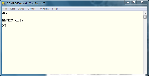
Start communication: Type ATZ in the terminal window and press enter to start communication with the OBD device. This sends the command to reset the OBD device. You should see some LEDs flashing on your card and then you should see the start command in the terminal window.
If the bad characters return, make sure you have the correct serial port settings in your terminal.
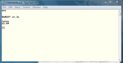
After communicating with your card properly, try reading the OBD-II UART system voltage. Type ATRV in the Terminal window, and then press enter. The card must send you the system voltage.
OBD commands consist of hexadecimal codes written in ASCII characters. Generally, these commands contain 2 or more hexadecimal number pairs, but several commands give only 1 number pair
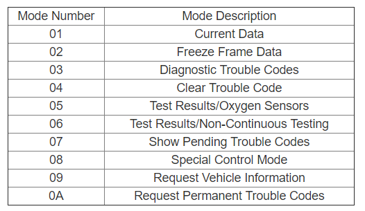
The first hex pair in the OBD command represents the OBD mode that should be used. The following hexadecimal pairs represent the Parameter ID (PID) to be read from the specified mode. Note that there are 10 OBD modes, but not all vehicles can use all 10 modes. You should check your vehicle’s protocols to see which OBD modes and parameter IDs are supported.
You can learn more about the functionality of OBD PIDs on the Internet. Some vehicle manufacturers also use their own custom parameters, so keep in mind that these are not a comprehensive list for your vehicle. The following is an appendix to the ELM327 AT Commands data sheet.
Probably the most important PID is 00. You can get a list of other PIDs that the tool supports by running this PID on any tool that supports OBD. Type 0100 in your terminal window, and then press enter. This command returns a list of which PIDs are supported in mode 01.
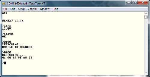
All OBD responses have a common general structure. The first response byte (0x41 in the example above) lists the desired mode in the command. The board sends the message as 0x40 + 0x01. The second byte is the desired parameter, in our example, 0x00. Other bytes are responses to the command. In this case, 0xBF, 0x9F, 0xA8 and 0x93 are vehicle-supported PIDs.
You can view the Mode and PID list from the link. https://www.outilsobdfacile.com/obd-mode-pid.php#mode_1_2
The data to be read through OBD in our project and the mode of this data and PIDs are given below.
Engine Speed: Mode: 01h, PID: 0Ch, Data Size: 2 Bytes
Enter 010C in the terminal window for testing and press Enter. Let’s remember the answer to the general structure. The first response is byte (0x40 + 0x01), ie (0x41). The second byte (0x0C) will be. The subsequent bytes give the engine speed.
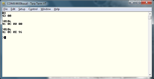
If you change the value of 0x0E 0x96 to decimal, you find the decimal value of 3734. This is actually 4 times the actual RPM. When the value is divided by 4, the engine speed can be 933.